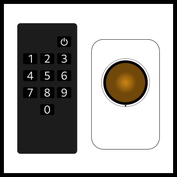
Flip clocks are cool. I got lucky and I scored a Solari Udine Cifra 5 flip clock off of a second hand marketplace for 100 EUR. The only problem was that the clock was a slave clock meaning that it needs an external master clock to keep time and send impulses to advance time. I don't have a master clock but thankfully nowadays it is easy to build one even with minimal skills using an Arduino based system. Bearing in mind that the clock is from 1975 (it says so in a sticker on the back) and it has probably never been serviced it runs amazingly well. Based on roughly one month of testing it can run for a few days before it loses a minute due to a mechanical issue.
Solari Udine Cifra 5 clock.
Bill of Materials
The bill of materials is quite short, and shouldn't set you back by no more than 100 euros.
- A real time clock module as Arduinos require an RTC module to keep accurate time.
- An h-bridge module to drive the elecromagnetic coil on the clock.
- An external 24 (or 12, depends on the model) volt source to drive the clock and the Arduino.
- A buck converter to reduce voltage to 7ish volts for the Arduino.
- An Arduino board. I suppose any module will do. I used an R3.
In addition to these you'll probably need a case as these won't fit in the clock case. Also, you will probably want some kind of an adapter to be able to connect the power source easily to the rest of the components.
How does the clock work?
Depending on the model the clock will require either 12 or 24 volt impulses. Some models even accept both (impulse voltage is selected using a jumper). The coil on my Cifra says it needs 24 volts. Some random internet source I saw somewhere (tm) stated that these clocks requires a two second impulse to advance time. The trick is that polarity must be swapped every minute, hence the h-bridge. The actual clock mechanism is far beyond my comprehension...
Wiring
The wiring diagram is shown below. As you can see it is really straightforward and requires minimal soldering if Dupont cables are used. It should be obvious by now that my knowledge on electricity and electrical circuits is limited to knowing that electricity is blue and it hurts and that electrical equipment require grey smoke to work, so use this at your own risk.
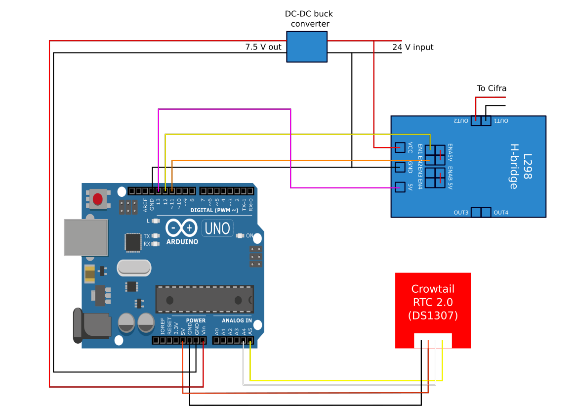
Wiring scheme.
Arduino code
Essentially what you need to do is to create a script that sends an impulse to the clock once a minute. The Arduino doesn't need accurate time (although it does need accurate timing, hence the RTC chip). Depending on your RTC module selection, you'll need to install one of the RTC library modules (note that these have to be included with double quotes instead of smaller than/larger than signs) and then tweak the script below if needed. The script is an infinite loop and it fires whenever it is one second past full minute. I included a check to prevent the script from running more than once. This control gets cleared when it is two second past full minute.
#include "RTClib.h"
#include <Wire.h>
#include "Time.h"

RTC_DS1307 RTC;
bool state = false;
bool controlCheck = false;

time_t syncProvider() {
  return RTC.now().unixtime();
}

void setup () {
  Serial.begin(57600);
  while (!Serial)
  Wire.begin();
  RTC.begin();
  delay(200);

  pinMode(11, OUTPUT); // in1
  pinMode(12, OUTPUT); // in2
  pinMode(13, OUTPUT); // 5v to h-bridge

  digitalWrite(11, LOW);
  digitalWrite(12, HIGH);
  digitalWrite(13, HIGH);

  setSyncProvider(syncProvider);
}

void loop () {
  if(second() == 1 and controlCheck == false) {
    if(state == true) {
      state = false;
      digitalWrite(11, HIGH);
      digitalWrite(12, LOW);
      controlCheck = true;

    }
    else {
      state = true;
      digitalWrite(11, LOW);
      digitalWrite(12, HIGH);
      controlCheck = true;
    }
  }
  if(second() == 2 and controlCheck == true) {
    controlCheck = false;
  }
}